Location: [CPSC 333] [Listing by Topic] [Listing by Date] [Previous Topic] [Next Topic] Data Design
This material was covered during lectures on February 25, 1997.
Suppose, now, that we are using ``structured'' (rather than object-oriented) development to analyse and design a system. Consider, again, the ``data'' component of the problem.
We've seen that, for the types of applications that are generally developed using these methods, an entity-relationship diagram and supporting data dictionary can be used to model the ``stored data'' requirements for the system.
We'll assume that these models have been used to specify the ``functional'' requirements for the system relating to stored data. Additional performance requirements that relate to stored data may also have been gathered; these concern the quantity of data that must be stored, as well as the expected rate of requests for various (predictable) kinds of operations on this data - and, possibly, bounds on the time that is allowed for the completion of these operations.
During ``architectural design'' we'll use the ERD to separate the stored data into a set of ``data tables,'' that might be stored (between applications of the system) as separate files, and that will probably also be implemented as separate data structures that are accessed when the system is in use.
We will also try to specify an ``interface'' between the data subsystem (that we're now trying to design), and the rest of the system to be developed. That is, we'll try to name a set of operations that will be supported by this subsystem, that the rest of the system can call, in order to access the data inside it. We'll also list inputs and outputs (and the orders in which they appear) for each operations, and we'll try to say ``what'' each of these operations must do.
Now, if this really is the kind of system that structured development was (apparently) intended for, then the stored data can be regarded as forming a set of data tables, such that each table has a fixed number of columns, such that all entries in any given column must have the same type, and such that the number of rows in each table is dynamic - rows can be added or deleted, and the entries in the rows can change, as the system is used. It's also possible to choose a set of columns (corresponding to a set of ``attributes'' for what's being stored) that forms a key - the values in these columns can't be the same for any two rows of the table. Thus, we could use a ``relational data base'' to store and access this data, relatively easily.
If this the case then the first part of data design - identifying a set of ``data tables'' is straightforward.
Two cases (involving relationships or associative objects) are mentioned in the second step, above. For binary relationships, the first case is applicable if (and only if) the relationship type is ``1:1,'' ``1:1c,'' ``1:M,'' or ``1:Mc.''
Now, it is necessary to define the ``interface'' between the data subsystem and the rest of the system. Some of the functions that should be included in the interface are easy to identify: For each data table that was created in the first step given above, and for each data table that was created in the second step that corresponds to an associative object, you will want to include at least the following operations:
It's likely that at least one ``list all'' operation will be needed, as well. It might also be desirable to support one or more ``list some'' operations, in which the input consists of (partial) values for a subset of the attributes, ranges of values, etc., and the operation returns a sequence of all the instances that are consistent with the inputs that were supplied. Additional operations are possible, as well; you'll need to consider the operations that the rest of the system is required to support, and the kinds of accesses to stored data that are needed to provide these operations, in order to decide which (additional) functions are required.
You'll also need to include most - but not all - of the above operations, for the data tables that were created in the second step and that correspond to relationships; it probably doesn't make sense to ``modify'' an instance of a relationship (since it doesn't have any ``non-key'' attributes whose values can be changed), but most or all of the rest of the operations that are listed above will be needed.
You should also consider operations, for relationships and associative objects, in which the primary key for one of the entities connected by the relationship or associative object is supplied as input, and in which a sequence of instances of the relationship (or associative object), that include the given instance, is returned as output. (More precisely, the output is probably a sequence of things including ``everything in the instance of the relationship or associative object, except for the values that were supplied in the input.'')
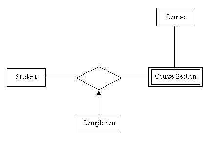
Consider Version Four of the Student Information System; an entity-relationship diagram for this system is as follows.

In the first step of the method (described above) for creating data tables, we would create three data tables - one each for ``Student,'' ``Course,'' and ``Course Section.'' The table for ``Student'' would include columns for each of the attributes of ``Student:'' ``ID number,'' ``first name,'' ``middle initial,'' and ``last name.'' Similarly, the data table for ``Course'' would include columns for ``discipline code,'' ``course number,'' and ``course title.'' Since ``Course Section'' is a weak entity that ``depends on'' the entity ``Course,'' the data table for ``Course Section'' would include columns for the primary key attributes of ``Course'' - ``discipline code'' and ``course number'' - as well as for the weak entity's own attributes - ``term,'' ``year,'' ``section number,'' and so on.
In the second step we'd consider all the relationships and associative objects. In this case there is only one of these and (since the first case described in this step doesn't apply) it will be necessary to add a new data table for it. This will have name ``Completion,'' and it will include columns for the primary key for ``Student'' - ``ID number'' - as well as the primary key for ``Course Section'' - ``discipline code,'' ``course number,'' ``term,'' ``year,'' and ``section number'' - and, finally, for the associative object's ``own''' attribute, ``grade.''
A list of ``interface'' operations can be obtained by considering each data table in turn, and applying the checklist given above.
Rather than including a ``List All Students'' operations, it might be more useful to include a ``List Old Students'' operation in which an ID number is supplied, and a sequence of all ID numbers that represent students in the data base and are less than or equal to the input ID, is returned as output - check the problem statement(s), and note that the method that's to used to ``delete old students'' is the same as it was for Version Two.
Another operation that might be useful, and that you might not discover by applying the checklist, would be a ``List Sections of Course'' operation, for which you'd supply a ``discipline code'' and ``course number'' as inputs (to specify an instance of ``Course'') and which returns as output a sequence of values for ``term,'' ``year,'' and ``section number'' - identifying all the ``course sections'' that correspond to the input.
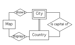
We won't consider this next example is as much detail as we did the first. Consider the Cartography system used in the first two assignments. An entity-relationship diagram for this system (that was part of the solutions for Assignment #1) is as follows.

When identifying data tables, we'd create tables for ``Map,'' ``City,'' and ``Country,'' in the first step that is described above. In the second step, we'd need to add new data tables corresponding the relationships ``shows'' and ``displays,'' as well, because these relationships have type ``Mc:Mc.'' However, we could include ``is capital of'' by extending an existing table (because the relationship's type is ``1:1c'') instead of creating a new one.
In particular, we could extend the the table for ``Country.'' Now, the primary key for ``City'' is ``country name'' and ``city name,'' so we might first think that it's necessary to add two columns to the table.
However, we know that the capital city for any given country is a city that's in that country - so, in fact, we only need to add one column to the ``Country'' table - for ``city name,'' in order to represent the ``is capital of'' relationship.
Again, you'd determine functions to include in an ``interface'' by applying the checklist given above, and then considering the operations that the entire system is required to support, to determine whether any of these ``interface'' operations aren't needed, and to determine whether any extra, less obvious, operations should be added.
This topic is, essentially, ``beyond the scope of this course:'' part of it has been addressed already, in CPSC 331, while the rest will be considered in detail in CPSC 461 and CPSC 471.
In particular, there are (at least) three significant cases that may arise.
In the first case, you can use a set of files to maintain the data between the times when the system is in use, and it's possible that it's sufficient to choose a file format that resembles (or mimics) the format of the ``data tables'' that are described above.
You will need to consider the performance requirements that are mentioned above, in order to choose data structures to maintain this data, when the system is in use. You might consider arrays, linked lists, search trees, or combinations of these. Use the performance requirements to decide which (if any) access operations should be made to be as efficient as possible, and note that each data structure has a different set of advantages and limitations. These were considered in CPSC 331. A good rule to remember here is that ``you shouldn't optimise, until you're certain that you need to.'' That is, always choose a simple approach (and data structure and algorithms) over a more complicated one, unless you're certain that the simple approach won't be adequate.
In the third and second cases, the material you need in order to continue ``detailed design'' will be covered in CPSC 461 and CPSC 471.
Location: [CPSC 333] [Listing by Topic] [Listing by Date] [Previous Topic] [Next Topic] Data Design