Location: [CPSC 333] [Listing by Topic] [Listing by Date] [Previous Topic] [Next Topic] ``First Cut'' Structure Chart for Example
This material was covered during lectures on February 26, 1997.
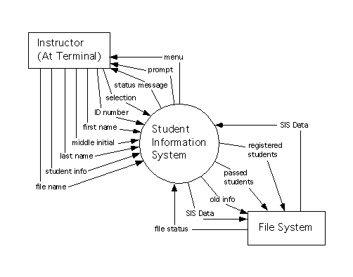
A set of data flow diagrams for a system resembling Version One of the Student Information System appears below. These diagrams are different from the set of data flow diagrams modeling essential requirements for this system because they include processes to support a simple menu-based interface for the system. They also show interaction with a ``File System'' to receive input from a text file (for system initialization) and to send output back to text files, for complex reports and on system termination. The diagrams reflect a decision not to use a relational data base to store system, data, but to use text files to store data between applications of the system. It also reflects an assumption that the quantity of data to be retained by the system is small enough so that all of it can be kept in main memory at once.
The context diagram for the system is as follows.

The level 1 data flow diagram for the system appears below.
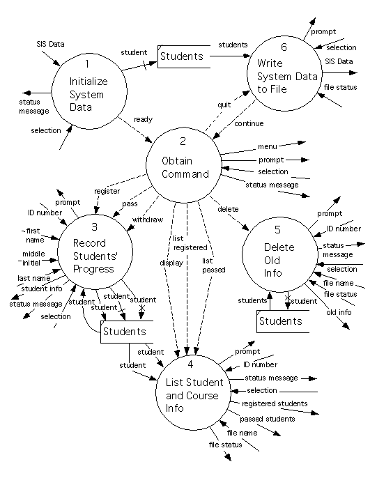
Process 1 is a ``bottom level'' process (that is, it has a process specification instead of a lower level data flow diagram). This process tries to read student data in from a text file, ``SIS Data.'' If it succeeds then it initializes the ``Students'' data store as empty, and then creates all the instances of ``Student'' listed in the text file.
If the file is corrupt (unreadable, or contains syntactically or semantically invalid data) then a status message is returned to the user, who is also asked whether he wishes to continue (answering ``Yes'' or ``No.'') If the answer is ``Yes,'' then the data area is initialized as empty, a ``ready'' signal is sent to the rest of the system, and this process terminates. If the answer is ``No'' then the entire system terminates immediately.
On the other hand, if the file is correct, then the data area is initialized using it, a ``ready'' signal is sent to the rest of the system, and Process 1 terminates.
Process 6 is also a ``bottom level'' process. This starts by communicating with the user, asking for confirmation that the system should terminate. If the answer is ``No,'' then a ``continue'' signal is sent to the rest of the system, and the process terminates.
On the other hand, if the answer is ``Yes,'' then information is read from the ``Students'' data store and used to create a ``SIS Data'' text file. An attempt is made to write this to the file system. If the attempt succeeds, then the system terminates. Otherwise, the user is informed of the problem and asks whether he wants to continue (in which case, a ``continue'' signal is sent back to the rest of the system) or to quit anyway (in which case the system terminates).
The remaining processes shown on this diagram are refined using lower level diagrams. The level 2 diagram refining Process 2 is as follows.
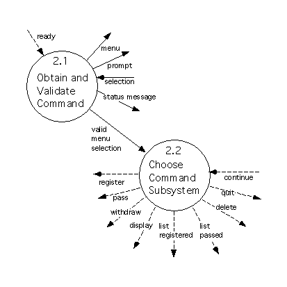
Both of the process shown here are bottom level processes. Process 2.1 repeatedly displays a simple menu (listing the commands that the system supports), prompts the user for a command, and checks that the input is one of the commands the system supports (reporting the problem, if it isn't), until a valid command has been received. This ``valid menu selection'' is then sent to Process 2.2. Process 2.2 repeatedly receives a menu selection from Process 2.1 and uses it to choose a subsystem to activate, terminating when once it's activated Process 6 (and this process hasn't sent a ``continue'' signal back again as a response).
The level 2 diagram refining Process 3 is as follows.
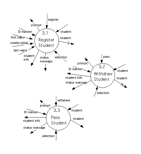
These processes send output (such as prompts) and receive inputs (such as ``selections'') that the corresponding processes in the set of diagrams modeling essential requirements, but they do resemble these processes, apart from that. Process 3.1 resembles the old Process 1.1, Process 3.2 resembles the old Process 1.2, and Process 3.3 resembles the old Process 1.3.
The level 2 diagram refining Process 4 is as follows.
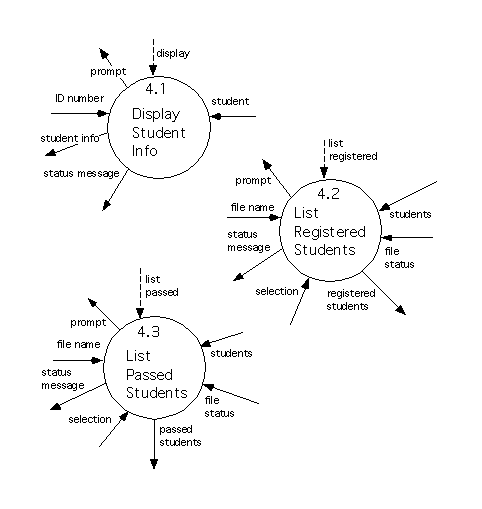
These are also bottom level processes that resemble processes in the set of diagrams for essential requirements, except for additional input and output. Process 4.1 resembles the old Process 2.1, Process 4.2 resembles the old Process 2.2, and Process 4.3 resembles the old Process 2.3.
Now, although Process 5 does resemble the old Process 3, it will be refined by a lower level diagram instead of a process specification. The level 2 diagram refining Process 5 is as follows.
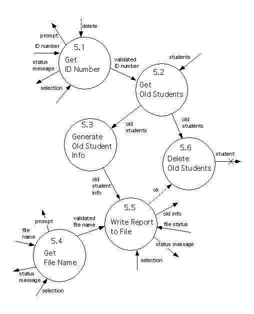
All the processes that are shown on this diagram are bottom level processes.
Process 5.1 prompts the user for an ID number, and checks the syntax of the ID number that the user returns. If this is syntactically correct then this is sent to Process 5.2, and Process 5.1 terminates. Otherwise the problem is reported to the user, who has the option of either cancelling the operation or trying again. The process repeats this until the user has either cancelled the request, or supplied a valid ID number.
Process 5.2 uses the ID number received from Process 5.1, and interacts with the ``Students'' data area, to select all the instances of ``Student'' (in the system) whose ID numbers are less than or equal to the one supplied by Process 5.2. The set of these instances is sent to Processes 5.3 and 5.6.
Process 5.3 removes some unneeded information from this set and uses it to compute an ``old student info'' report, which is sent to Process 5.5.
Process 5.4 resembles Process 5.1, except that it prompts for and validates a file name, instead of an ID number. If a valid file name is obtained, then it is sent to Process 5.5.
Process 5.5 generates a text file using the ``old student info'' it received from Process 5.3, and tries to write it to the File System, using the file name that was supplied by Process 5.4. If this attempt succeeds then an ``ok'' signal is sent to Process 5.6. Otherwise (when the write failed), the problem is reported to the user, and the user is asked whether the old students should be deleted anyway. If the user's answer is ``Yes'' then an ``ok"' signal is sent to Process 5.6; this signal isn't sent, otherwise.
Finally, Process 5.6 receives a set of ``old students'' from Process 5.2. If it also receives an ``ok'' signal from Process 5.5, then it deletes all the students in the set of ``old students'' from the ``Students'' data area; otherwise it makes no change.
Note that this is not a good example of a leveled set of data flow diagrams: At least some of Processes 1, 3.1, 3.2, 3.3, 4.1, 4.2, 4.3, and 6 should really be refined by lower level data flow diagrams instead of by process specifications, and it might not be necessary to used quite as many processes to refine Process 5 as are shown above. A more sensible set of diagrams (and process specifications) for this system would probably include more diagrams and processes than are shown here; the ones used here are complete enough to serve as a useful example for ``structured design'' (and it will take less time to apply ``structured design'' to these, than it would to apply it to a more sensible set of diagrams for the same system).
We will begin with one large data flow diagram for the entire system. As previously described, this can be obtained by starting with the context diagram and repeatedly replacing processes with the lower level diagrams that refine them, until every process shown on the diagram is refined by a process specification instead.
The diagram (of this type) that corresponds to the above example is as follows.
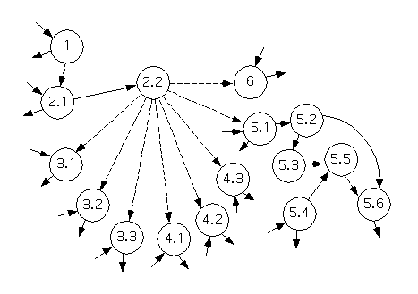
Now, we'll begin to reply the recursive process in order to map DFD processes to modules on a structure chart.
An inspection of the above diagram(s) suggests that Process 1 is active once, before all the others, and terminates before any others begin. As well, the only direct communication between Process 1 and the rest of the system is the transmission of a control signal, ``ready.''
Therefore, we'll start by deciding that the large diagram displays two independent subsystems:
Since we've identified independent subsystems, this is straightforward: We'll simply break the diagram into two subdiagrams, each showing one of the two subsystems listed above.
This is also straightforward for independent subsystems: We will create a main module (since one hasn't been produced already), and we'll name this ``Student Information System.''
We won't map any modules to processes yet. Instead, we'll apply this method, recursively, to each of the diagrams obtained above.
The piece of the structure chart generated so far, with ``off page connectors'' in place of the subcharts we'll create recursively, is as follows. (If you're using Netscape or another powerful browser then you should find that the ``off page connectors'' are clickable, so that you can use them to move from one part of the structure chart to another).
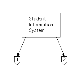
Now, we'll apply this method to the diagram for the first subsystem.
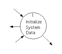
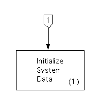
Since the diagram includes only one process, it's clearly trivial, so we'll just map it directly to a module.
The resulting structure chart is as follows.
In this third iteration, we'll apply the method to the second subsystem that was obtained during the first iteration of the method.
The data flow diagram to be processed is as follows.
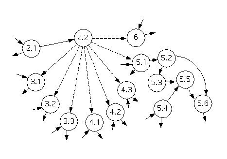
A consideration of the shape of this system, and the description of Processes 2.1 and 2.2, suggests that this diagram has transaction flow.
When partitioning a data flow diagram with transaction flow, we must identify the transaction center, command acquisition path, and activity paths. The above diagram includes a transaction center, a ``command acquisition path'' that includes only a single module, and eight ``activity paths:''
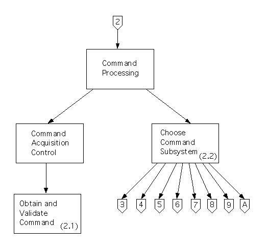
During first level factoring, we will create a main module (called ``Command Processing'') for this subsystem, and two modules that it controls: a controller called ``Command Acquisition Control,'' and a module that corresponds to the transaction center and that has the same name (``Choose Command Subsystem'').
During second level factoring, the processes on the command acquisition path will be mapped to modules that are controlled (directly, or indirectly) by the ``Command Acquisition Control'' module created above. In this case, there is only one module on the command acquisition path - Process 2.1 - so we'll create a module with its name (``Obtain and Validate Command'') and we'll make this a child of the controller.
The activity paths will be processed recursively; the main modules of their structure charts will be made children of the transaction center's module in order to connect all the structure charts together.
The (piece of the) structure chart that we've obtained is shown below. It includes the modules that were created during first- and second-level factoring, and ``off page connectors'' (leading down below it) that will be connected to the structure charts for activity paths that were mentioned above.
The data flow diagram for this subsystem is trivial - it includes only one process. The structure subchart that corresponds to it is as follows.
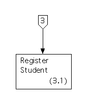
The data flow diagram for this system is also trivial; its structure subchart is shown below.
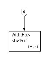
The structure chart for the third activity path, which is also trivial, is as follows.
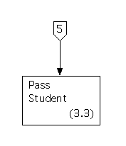
Here is the structure chart for the fourth (trivial) activity path.
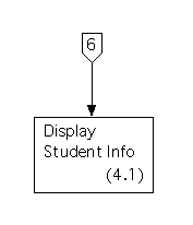
The structure chart for the fifth activity path is as follows.
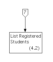
The structure chart for the sixth activity path is shown below.
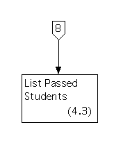
The tenth iteration will apply the method to the data flow diagram for the seventh activity path.
The data flow diagram for this subsystem is as follows.
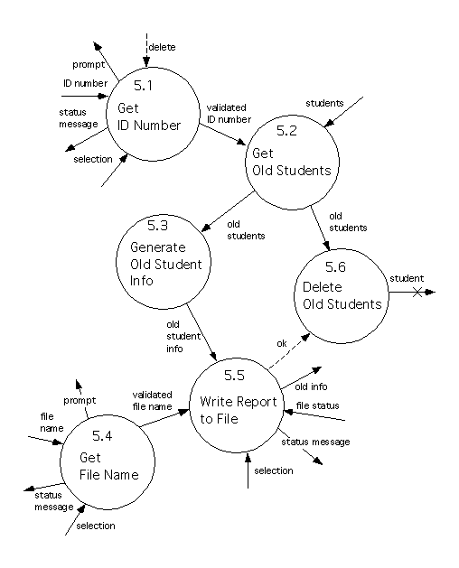
This diagram is nontrivial, and it doesn't seem to include independent subsystems or transaction flow. Therefore, we'll decide that it has transform flow.
In order to partition a diagram with transform flow, we must decide whether each process is an ``input flow'' process, an ``output flow'' process, or in the ``transform center.''
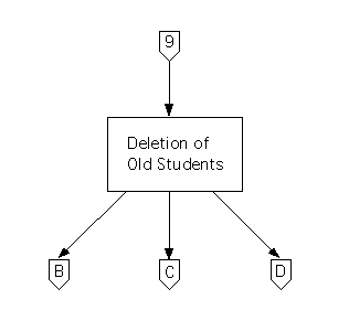
During first level factoring we'll create a main module for this subsystem, called ``Deletion of Old Students,'' and we'll create three controllers that it can call: an ``input'' controller called ``Old Student Input Acquisition,'' a ``processing'' controller called ``Old Student Processing,'' and an ``output'' controller called ``Old Student Reporting.''
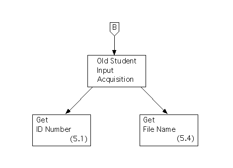
During second level factoring, we'll map each of the ``input flow'' processes to a module (with the same name) that's controlled, directly or indirectly, by the above ``input'' controller.
In this case there are two ``input flow'' processes, and they both pass data across the input flow boundary (to output flow processes or to processes in the central transform), so we'll make the module for each process a child of the ``input'' controller.
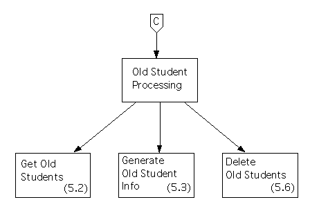
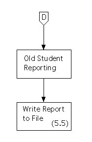
We'll also create modules for each of the ``output flow'' processes and will have them controlled by the ``output'' controller. In this case, there is only one such process, so we'll make its module a child of this controller.We'll apply the method recursively to the set of processes in the transform center. However, there are only three of these, so they form a ``trivial'' data flow diagram - so we'll skip a step and finish the job, and make the module for each a child of the ``processing'' controller, as the description of processing a trivial diagram should suggest.
The top of the structure chart for this system (showing the main module, and off page connectors that link to the system's controllers) is as follows.
The subchart for input flow is as follows.
The subchart for processing is as follows.
Finally, the subchart for output flow is shown below.
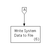
The structure chart for the eighth (trivial) activity path is as follows.
Finally, a data area should be added for the data store that is shown on the data flow diagrams. This would be drawn at the bottom of the structure chart.

Control connections should be added, from the module for each process that accesses the data store (on the data flow diagrams), down to this data area: namely, the modules for Processes #1, #3.1, #3.2, #3.3, #4.1, #4.2, #4.3, #5.2, #5.6, and #6.
Data and control signals should be added for each of the data and control flows on the data flow diagrams that flow between two processes, or between a process and a data store.
For each data (or control) flow between a process and a data store, you'll have added a control connection from the module for the process down to the data area, already. Draw a single data (or control) signal for the data (or control) flow, and showing at as moving along this control connection.
It won't always be true that there's a control connection between the modules that correspond to two processes, such that data flows between them. However, since the modules we've added to the structure chart form a hierarchical ``tree'' structure, these two modules will have a unique ``lowest common ancestor'' in the tree. Show the data (or control) signal as moving along control connections, up from the ``source'' module to the common ancestor, and then back down from the common ancestor to the ``destination.''
A redrawn structure chart, showing connections to the data areas and the data and control signals that should be added, is also available.
Location: [CPSC 333] [Listing by Topic] [Listing by Date] [Previous Topic] [Next Topic] ``First Cut'' Structure Chart for Example