Location: [CPSC 333] [Listing by Topic] [Listing by Date] [Previous Topic] [Next Topic] Path Testing
This material was covered during lectures on March 26, 1997.
Path Testing is a structural method for unit testing. Its goal is to ensure that all statements in the program, and both sides of every (two-sided) test in the program, are executed or followed by at least one test.
It can be applied to source code or (as below) to reasonably detailed pseudocode, provided that all tests and loops in the source code are explicitly shown in the pseudocode as well.
Perhaps this section should be entitled ``Lack of Reference,'' because the material presented here is different from what appears in many software engineering texts. In particular, many texts - including Pressman's Practitioner's Approach, present a method called Basis Path Testing, which is similar to the method that's presented here in some respects.
The best thing that can be said about ``Basis Path Testing'' (that comes to mind) is that it ``forces you'' to try to develop a few more tests than ``Path Testing'' requires. However, it doesn't seem to provide significantly better coverage than Path Testing does, and appears to be more difficult to describe, understand, or apply. It won't be used (this year) in this course.
``Path Testing'' (and, indeed, ``Basis Path Testing'') includes two major steps:
Each of these steps is described below.
A Flow Graph for a module is a directed graph, with unique ``source'' and ``sink'' nodes (unique nodes with zero incoming edges and with zero outgoing edges, respectively). It is similar to, but simpler than, a flow chart: Each node in the graph (except, possibly, the ``sink'') corresponds to a statement or (two-sided) test in the source code or pseudocode for the module; if the ``sink'' node doesn't correspond to a statement in the code, then it is an extra stop statement that has been added to ensure that the program has a well defined (and unique) exit point. Each edge in the program corresponds to a a possible transfer of control, from the edge's source node to its destination node.
Flow graphs can be defined for a number of control structures that are typically used in ``structured programming,'' if a programming language like Pascal or C is used.
A sequence of a pair of statements,
s1; s2
(such that, if s1 is executed then s2 must always be the next statement executed after that) has the following flow graph.

You can use this template to develop flow graphs for larger programs, as well. In particular, if you have a program that includes two subprograms, s1 and s2, such that s2 is always executed after s1 terminates, then you can obtain a flow graph for the larger program by taking the flow graphs for the two subprograms, and and adding an edge from the ``sink node'' in the flow graph in s1 to the ``source'' (or ``start'') node in s2.
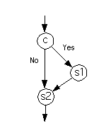
The flow graph for the program
            if c then
              s1
            end if
            s2
where c is a (two-sided) test and s1 and s2 are statements (or subprograms) looks as follows.

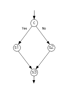
The flow graph for the program
            if c then
              s1
            else
              s2
            end if
            s3
is as follows.

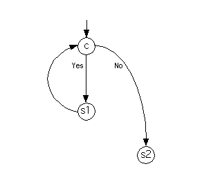
The flow graph for the program
           while c do
             s1
           end while
           s2
is as follows.

One common error is to add more edges. For example, one common mistake would be to add another edge, directly from the node for s1 to the node for s2, in the flow graph given above. There shouldn't be such an edge, because the program will never transfer control directly from statement s1 to statement s2 - it'll always perform the test c for the while loop, in between.
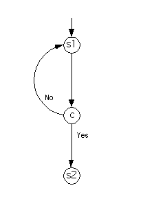
Finally, the flow graph for the program
           repeat
             s1
           until c
           s2
looks as follows.

You can generate the flow graphs for other control structures by rewriting them (making as few changes in structure as possible) using the control structures listed above.
For example, the program
          case x of
            v1: s1; break
            v2: s2; break
            default: s3
          end case
          s4
could be rewritten as
          if (x is equal to v1) then
            s1
          else
            if (x is equal to v2) then
              s2
            else
              s3
            end if
          end if
          s4
Then, you could generate a flow graph that represents the original program by working with the new one, using the flow graph for if-then-else that is given above.
Now, given these flow graphs (and using them as ``templates''), you can generate flow graphs for more complicated programs, either by working from the bottom up (producing the flow graph for a loop body, and then using the above template a while loop to obtain the flow graph for the entire loop, etc.) or from the top down (choosing a template that matches the structure of the entire program, and then building and inserting flow graphs for the subprograms that are left over).
The cyclomatic complexity of a flow graph (and the program represented by one) is a measure of the ``complexity'' of the program. It can be computed in several ways - and you can compute the cyclomatic complexity using each of the formulas given below, and then compare the values obtained, as a check that the flow graph has been correctly formed.
If you think of the edges of a flow graph as delineating (or separating) connected components (or spaces) in the plane (or, on your computer screen, or on the blackboard), then the cyclomatic complexity of the flow graph is equal to the number of regions that are separated by these edges, including the ``rest of the plane'' that surrounds the graph.
If the flow graph has e edges (not including an edge coming in from ``nowhere'' that indicates the ``source'' node, if one is shown) and it has n nodes, then the cyclomatic complexity of the flow graph is e - n + 2.
If the flow graph includes p two-sided tests (and no three-sided tests, four-sided tests, etc.) then the cyclomatic complexity of the flow graph is p + 1. These tests are easy to find - they correspond to the nodes that have two outgoing edges (instead of only one or zero).
Now, in order to use a flow graph to design tests, you should try to choose an input for the corresponding module such that execution of the module's code on the input would include the execution of at least one statement (or choice of the outcome of a test) that causes an edge in the flow graph to be ``followed'' or ``covered,'' that hasn't been followed by previous tests.
Add this input (and its expected output) as a test for the program, and note all the edges in the flow graph that are ``covered'' by it.
Repeat this strategy until all the edges of the flow graph have been used.
Note that it's likely that you can discover one (or a few) test(s) that will ``cover'' most or all of the edges immediately. You should avoid these, and look for tests that cover as few new edges as possible, instead. The number of tests you use will be small in any case - and using a larger number of simpler tests will generally make it easy to locate errors in the source code, when tests fail.
In general, the number of tests obtained using this method will be at most the cyclomatic complexity (and you should try to make the number of tests used ``close to'' the cyclomatic complexity, if you can see how to do this).
As previously mentioned, Basis Path Testing is a similar, but more complicated, method described in various software engineering textbooks. This method might allow you to discover a few more ``independent'' tests to add, but it can be shown that this method never requires more tests than the cyclomatic complexity of the flow graph, either.
Since one definition of cyclomatic complexity if ``number of two-sided conditions in the program, plus one,'' it should be clear that the cyclomatic complexity of any nontrivial (and sensible) program will be less than or equal to the number of statements in the program. Thus - while it hasn't been proved in this course - it can be shown that the number of tests that one can obtain using either ``Path Testing'' or ``Basis Path Testing'' is at most the number of statements in the program (plus one, in extreme and completely unrealistic cases).
This method will be applied to an example on a separate page.
A lab exercise based on this material is also available.
Location: [CPSC 333] [Listing by Topic] [Listing by Date] [Previous Topic] [Next Topic] Path Testing