|
|
VLAB Home |
|
Bezieredit is a utility for editing surfaces consisting of Bézier patches. The patches can exist sepatately, or joined with various levels of continuity. All the work is done in a single view which can be rotated about the xy-axes to view and edit the surface from any angle. All manipulation of the surface is done through the control points of the Bézier patches.
The Bezieredit program is invoked as:
> bezieredit [surface_file]
A window is displayed as in Figure 1, showing the wire-frame surface, its control points, a reference grid, xyz-axes and the connection point. If the filename arguemnt specifies a valid surface file, the file will be loaded and the view will be appropriately scaled to the surface. Otherwise, a default view will be opened with no Bézier patches.
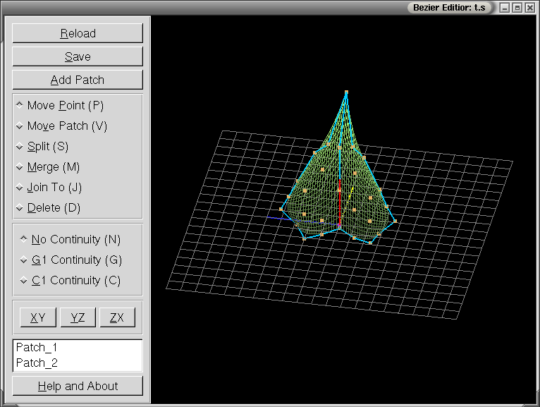
On the left of the view is the control panel, through which the functions and editing modes controlled, as displayed in Figure 1.
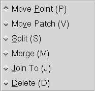
Editing the patches is done while in specific editing modes, as selected on the control panel, as seen in Figure 2. Each mode has an associated hot key (listed in the parentheses that follow) to speed up transitions when editing. The cursor will change to reflect the current editing mode.
When continuity is enabled, all the patch manipulation will occur under the continuity constraints. Control points will be modified automatically as needed to ensure that the constraints are retained around the edited points. Like the editing modes, there are hot keys associated to these for ease of transition.
The XY, YZ and ZX will snap the view to the xy, yz and zx planes respectively. This corresponds to front, side and top views.
The patch names, as found in the data file, are listed on the control panel. Selecting a particular patch naem will cause the corresponding patch to be highlighted in the view. Highlighting is strictly for making a particular patch more visible to ease editing and does not have any effect in the data.
Occasionally the user will want to manipulate a point in the plane that happens to be occluded by other control points. The solution is to double-click that point in any view where it is visible. This turns that point into the 'sticky-point'. When the sticky point is occluded by other points, selecting the area where it is will cause the sticky-point to be selected instead of those that occlude it as would be otherwise expected. The point can be returned to normal by selecting a new sticky point or by double-clicking on it again.
The Bezieredit popup menu is controlled using the right mouse button. The menu items denote the various elements which can be viewed. Any item can disabled or enabled to hide or show it in the view. The menu contains the following items:
The up and heading vectors attach to the connection point. The wire-frame and shaded models of the surface are mutually exclusive, selecting one, disables the other.
The colours and sizes used in bezieredit can be configured be editing the configuration file in VLAB. In the VLAB conguration directory ($VLABCONFIGDIR), there is a file called 'bezieredit' that may contain a line entry for each configurable colour. Each colour entry needs four values for red, green, blue and alpha colour components, scaled from 0.0 to 1.0. The fourth value, alpha, is currently unused, but is still required. The sizes are a single floating point number and the divisions are integers larger than four.
An example entry would then be background: 0.0 0.0 0.0 or Point Size 5.0 which would give a black background.
The creation of a complex surface requires the use of multiple patches. Adjacent patches are connected along shared edges. In order to determine which patches share the edge, a patch neighborhood is defined. Each patch can have up to eight neighbors as shown in Figure 3.
Once an arbitrary orientation has been chosen for the surface, adjoining patches can be considered to be above and to the left, AL, above, A, above and to the right, AR, to the left, L, to the right, R, below and to the left, BL, below, B, or below and to the right, BR, of a given patch.
These abbreviations are used in the surface description file when defining adjoining patches (see the example file shown below). The neighboring patch name must be specified next to the corresponding abbreviation, or the symbol "~" must be used, which represents no neighbor.
In order to place the surface at a location in 3D space at the required orientation, four geometry parameters need to be specified as shown in Figure 4. The contact point (CP) is the point which is aligned with the turtle's current position when drawing the surface. The end point (EP) is the point at which the turtle is positioned once the surface has been drawn. The orientation of the surface is specified by the heading vector (HV) and up vector (UV).
The first section of a surface description file contains information about the surface as a whole. This includes the minimum and maximum value pairs for the x, y, and z values of the bounding box for the surface, the geometry parameters (i.e., contact and end points, heading and up vectors) (see Figure 4), and a scaling parameter (giving the size to be considered as equivalent to the step size in cpfg). This is followed by groups of 9 lines, each describing one component patch. A group consists of a patch name, patch-specific rendering information, three lines of patch neighborhood information (see Figure 3), and four lines of patch control points, each line defining one row of four points.
For example the file leaf.s may contain the following lines:
| -35.00 35.00 -7.50 81.29
-7.50 21.85
CONTACT POINT X: 0.00 Y: -2.52 Z: 0.00 END POINT X: 0.00 Y: -2.52 Z: 0.00 HEADING X: 0.00 Y: 0.99 Z: -0.14 UP X: 0.02 Y: -0.14 Z: -0.99 SIZE: 86.29 Patch_1 TOP COLOR: 0 DIFFUSE: 0.00 BOTTOM COLOR: 0 DIFFUSE: 0.00 AL: ~ A: ~ AR: ~ L: ~ R: ~ BL: ~ B: Patch_2 BR: ~ -25.0 0.0 -5.0 -35.0 10.0 -5.0 -30.0 20.0 -5.0 -25.0 30.00 -2.5 -20.0 -7.5 -5.0 -20.0 10.0 -7.5 -20.0 25.0 -5.0 -15.0 50.00 0.0 -10.0 -5.0 -5.0 -10.0 15.0 -5.0 -10.0 40.0 -2.5 -7.5 55.00 2.5 0.00 -2.5 0.0 0.00 25.0 0.0 0.0 55.0 0.00 0.0 81.29 21.85 Patch_2 TOP COLOR: 0 DIFFUSE: 0.00 BOTTOM COLOR: 0 DIFFUSE: 0.00 AL: ~ A: Patch_1 AR: ~ L: ~ R: ~ BL: ~ B: ~ BR: ~ 0.00 -2.50 0.00 0.00 25.0 0.00 0.00 55.0 0.0 0.0 81.29 21.85 10.0 -5.00 -5.00 10.0 5.1 -5.00 10.0 40.0 -2.5 7.5 55.00 2.5 20.0 -7.50 -7.50 20.0 10.0 -7.50 20.0 25.0 -5.0 15.0 50.00 0.0 25.0 0.00 -5.00 35.0 10.0 -5.00 30.0 20.0 -5.0 25.0 30.00 -2.5 |
Colin Smith - Bezieredit implementation and documentation vL1.0
J. Hanan, I. Hernadi and P. Prusinkiewicz - File Format (from the orignal ISE documentation)
|
|
VLAB Home |
|