|
|
VLAB Home |
|
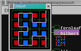
Object manager is a tool used to manipulate the internals of a specific object. When object manager is invoked on a VLAB object, all files constituting this object are copied to a temporary space, called the lab table, where the user can safely modify them without worrying about destroying the original. The set of possible actions on an object is read from its specifications file, displayed on the screen as a pull-down menu. The user can then perform actions on an object by choosing items from this menu, without any detailed knowledge of the programs and data files involved in these actions. The changes made to an object while it is on the lab table can be saved back to the database, added to the database as a new extension, or ignored altogether. The menus are available by pressing the right mouse anywhere on the object's icon in the object manager's window (refer to figure 2 below).
The Object Manager can be invoked on any object or hyperobject in the database by double-clicking the left mouse on the objects folder symbol (refer to Browser).
The Object Manager performs the following tasks:
The tools associated with the object are defined in two files: the object's specifications file, and the generic object file residing in the vlab config directory.
The specifications file serves three purposes:
Selecting a menu item allows the user to apply a tool to the object as a whole, without detailed knowledge of the program or the component files involved.
An example specifications file is given here:
; files moved to lab table fractal.l fractal.v fractal.a panel.l fractal.map * ; menu headings and tools to invoke image:
|
The first section, terminated with a single asterisk on a new line, lists all the files associated with the object, one per line. Two additional files are assumed to be included in every object: the icon file (refer to Icon), and the specifications file itself. The files in table 1 are shown in blue text.
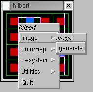
A menu description follows. It specifies each menu item, using tabs to indicate successive levels in the menu hierarchy and colons to terminate the entries. Menu items must not contain spaces. Each menu item is either followed by a sub-menu item or by an executable Linux command. Thus, according to table 1 above, selection of the item image followed by the item generate from the menus invokes the plant modeling program cpfg with the argument data files fractal.l, fractal.a and fractal.v . For example, the menu hierarchy shown in figure 2 below was created using the specifications in table 1 above. The menu headings in table 1 are shown in red, and the execution command arguments are shown in green.
The generic name, PALETTE, shown in purple in table 1, is assumed to have been defined in the object file, which describes tools commonly used in the virtual laboratory. Thus commonly used tools need to be specified only once, in one system-wide file. Refer to Object Configuration File.
Comments may be inserted in this file. Lines that begin with a semicolon are treated as comments. Comments in table 1 are shown in black text.
In addition to the items defined in the specifications file, the menu displayed by the object manager always includes a Utilities submenu and a Quit option.
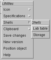
The Utilities submenu includes the following menu items:
| Icon | |
|
invokes an interactive tool for creating the object's icon (refer to Icon). |
|
rereads the icon file, so that changes take effect |
|
Specifications |
|
|
allows user to edit the specifications file, using the default editor |
|
rereads the specifications file, so that changes take effect |
| Shells | |
|
opens a Linix shell using the lab table directory in /tmp |
|
opens a Linix shell using the original object directory |
| Clipboard | |
|
opens a file selection panel and places the selected file name in the clipboard's queue of file names |
|
removes the next file from the clipboard and copies it to the current object on the lab table |
|
shows the contents of the clipboard |
|
Save changes |
saves changes to the original object |
| New version | creates an extension to the object |
| Position object | positions the selected object in the middle of the Browser window |
| Help | displays this document (not yet implemented) |
The lab table is a temporary directory normally created in /tmp. All files listed in the specifications file are copied to this directory and as tools are selected from the object menu they are applied to these temporary files, leaving the original files untouched. Users may modify parameters and change the object's definition by manipulating the data files in the object on the lab table. New tools, with accompanying data files, may also be added to the object by editing the specifications file.
Before removing the object from the lab table (by selecting Quit from the menu), the user must decide whether the modified object should be permanently stored. It may be stored as a replacement of the original object, or as an extension of that object. If an extension is requested, the user is prompted for its name and a new directory is created in the ext directory of the original object. In both cases, the files on the lab table are compared with the files in the object's prototype. Files that differ from the prototype are copied to the object's directory; the remaining files are created by establishing Linux symbolic links to the corresponding files in the prototype.
Each object has an icon. An icon is simply a small snapshot of the model which serves as a quick way to recognize a particular object. The icons are shown as thumbnails in the Browser, and are also shown in the Object Manager window.
Snapicon can be used to take a snapshot of a model, as shown in figure 4. Snapicon can be invoked by selecting Utilities then Icon then Snap from the Object Manager popup menu. The red snap-box can be moved by pressing on the border with the right mouse button and dragging to the desired location. To snap, depress the SHIFT key while clicking the left mouse on the green and grey Snapicon applet. The icon must be saved in the file icon in the object's directory. Snapicon's popup menu is available by pressing the left mouse on the green and grey Snapicon applet, where the Save Icon option can be selected.
![]()
The object file is a configuration file for the Object Manager, and is located in the VLAB config directory. It describes generic tools that may be used within an object's specifications file. Entries in the object file may be accessed by all objects in the virtual laboratory, thus eliminating the need for providing details of commonly used tools in each object. The object file resides in the vlab config directory. Entries in this file consist of a generic name, plus a list of tools. The list resembles the tool descriptions in the specifications file. Each entry in the object configuration file has the following format:
Several tools may be associated with a single generic name. Entries must be separated by a blank line. The parameters to be used with the tool are not specified on the command line in the object file. They will be appended to the command using arguments in the specifications file.
For example, PALETTE may be defined as follows:
The above global definition will be substituted for each occurrence of the word PALETTE in the specifications file. Such global definitions facilitate customization of the lab for each system configuration.
The object file may also include comment lines and global definitions. Comments start with a semicolon followed by any text on the same line. Comment lines may be inserted anywhere in the file.
Global names may be defined using the syntax:
#define SYMBOLNAME definition_string
where definition_string is a Linux command to execute.
For example:
#define EDITOR emacs
These definitions must occur at the beginning of the file.
#define OBJED emacs -geometry 80x24 #define OBJSHELL xterm -fg yellow -bg black ; Global Tools EDIT edit:
edit:
bezieredit:
|
The following procedure can be used to customize the editors used by the object manager.
| The first two lines of the object file define what editors are to be used by default. The names OBJED and OBJDEMOED are reserved and interpreted by the object manager when invoking shells for editing. OBJED is for regular editing and OBJDEMOED is for editing while performing demos (the font size is bigger).By default, they are set to the vi editor. |
|
#define OBJED xterm -bg 'black' -fg 'white' -name 'vlab editor' -geometry 80x24 -fn '*bold*18*' -e vi |
| If you wish to use a different editor (such as emacs), change the two lines, for example: |
|
#define OBJED emacs -font "-*-courier-medium-r-*-*-14-*-*" -geometry 80x24 |
Note that the program you specify must open its own window or be run inside of a shell. Since emacs does, it can be listed as above. Since vi doesn't, the lines must open a shell which then runs the editor.
Note that the names OBJED and OBJDEMOED can be used in the remainder of the object file like any other names.
L. Mercer. The Virtual laboratory. Master's thesis, University of Regina, Regina, Canada, 1991.
L. Mercer, P. Prusinkiewicz, J. Hanan. The Concept and Design of a Virtual Laboratory. In Graphics Interface '90 Conference proceedings, pages 149-155. Canadian Information Processing Society, 1990.
Jin Xiao - Object Manager Implementation
I. Hernadi, L. Mercer, P. Prusinkiewicz - Object Manager Documentation
Selected routines for image manipulation copyright 1994 by John Bradley. Used with permission.
1. The Copy and Paste commands are not implemented (but Browser items provide similar functionality).
2. Files may be removed, renamed or imported using the Linux file system, but the user must remember to update the specifications file accordingly, otherwise the new files will not be saved with the object.
3. The specifications and object files must have tabs placed correctly, spaces won't do. The menus will not be created properly if these files contain spaces instead of tabs, and no warning messages are generated.
4. When the user quits the object and there are too many files on the lab table to report to the user, the window gets so big that buttons on the dialog cannot be seen. This prevents the user from quitting the object.
5. The Help facility is not yet implemented.
|
|
VLAB Home |
|
