Location: [CPSC 333] [Listing by Topic] [Listing by Date] [Previous Topic] [Next Topic] Completing the Specification of Functional Requirements
Some of this material was covered during lectures on February 14, 1997.
Note that the notation (and symbols) for the various parts of an object-oriented specification described below seem to vary even more widely than the notation for structured development. Some of the notation and symbols used below (such as the pictures for ``message threads'') are taken from one ``object-oriented analysis'' method, or another; others (including data flow diagrams, and the format for data dictionary definitions) are simply borrowed from structured analysis, in order to avoid introduction of more notation that you might not ever see again.
No specific method (or what it includes in a specification) is described here. Instead, several components that you might find in an ``object-oriented'' specification are listed, along with brief remarks about the methods that do (or don't) include them.
An ``object-oriented'' specification will give a general (or overall) picture of the system by providing a problem statement, possibly a context diagram, and a class diagram.
This is the same as the kind of ``problem statement'' that has been used to begin structured analysis (and, it would be included as part of a specification that's prepared using ``structured analysis,'' as well).
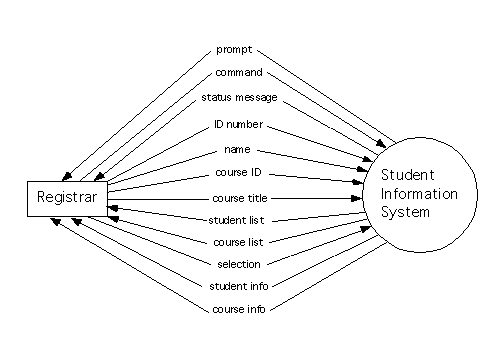
This is also the same as the ``context diagram'' that would be part of a leveled set of data flow diagrams that you would include in a ``structured'' specification for this system. It makes it easy to identify the user of the system, and the inputs and outputs that users will provide.
Some references for ``Object-Oriented Analysis'' (including Pont) recommend that this be included, while others (including Coad and Yourdon) don't.
For example, the context diagram for Version Two of the Student Information System might look like the following. (This version assumes the use of an interface that includes menus, such that the user can choose some inputs by making menu selections; we'll probably need to have specified at least some details of the interface by now, in order to have selected the services that will be shown on the class diagram.)

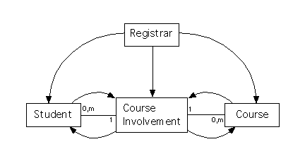
The components of a class diagram and its creation have already been discussed. Here is a class diagram that might be obtained for Version Two of the Student Information System, once all its events (and their message threads) have been considered, and all message connections have been added.
The event list, and the message threads identified for these events, will be useful for system testing, so it's worthwhile to include them in the requirements specification.
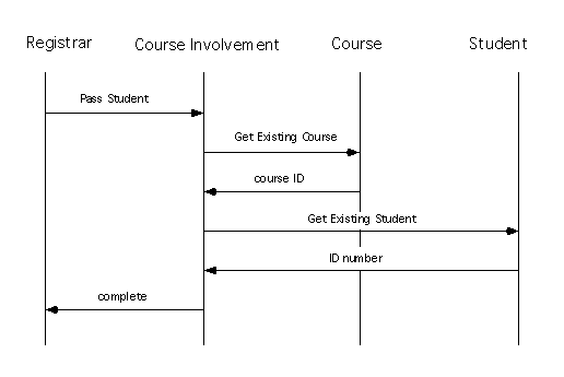
Object-oriented analysis methods include several different ways to specify message threads using pictures. For example, Rumbaugh's ``OMT'' method uses pictures in which classes are represented as vertical lines, and messages (and responses) are shown as horizontal arrows between these lines, that are labeled with the name of the message being sent, or the name (or, possibly, value) of the response returned. The arrows are shown, moving down the page, in the order in which messages and responses are sent.
For example, a message thread corresponding to a ``normal'' (error-free) response to an event ``Student Passes Course'' was used recent as an example, to show how to identify message connections and services; a picture of this message thread might look, roughly, like the following.
Some object-oriented analysis methods (including Coad and Yourdon's) don't include the use of a data dictionary at all; others (including Rumbaugh's) do, but use a ``data dictionary'' that's quite different from the kind of ``data dictionary'' we've seen so far in CPSC 333.
For example, in Rumbaugh's OMT method, the ``data dictionary'' simply lists the names of classes, in alphabetical order, along with a paragraph for each class that describes what it is supposed to represent, along with any important restrictions or assumptions about its use.
Finally, Pont's method ``Object-Oriented SADIE'' does seem to include a data dictionary that resembles the kind of data dictionary that Pont includes for his version of ``structured analysis,'' presumably including definitions for classes and attributes, and including information about the ``type'' of each attribute, as well.
It is necessary to provide a more detailed specification of each of the classes shown on the class diagram, as well. In particular, the class's attributes and services must be specified.
A list of the class's attributes should be provided. If a ``system-level'' data dictionary including this information isn't included, then the ``data types'' for the attributes should be provided here, as well.
You might do this by including a (shorter) ``data dictionary'' for each one of the classes shown on the system's class diagram. Since it's supposed to provide information about data types, this ``data dictionary'' should probably resemble the ``data dictionaries'' we've seen in this course (rather than the less formal kinds of dictionaries mentioned above, in the discussion of ``system-level'' data dictionaries for use with OMT).
The services, that the class - and its objects - provide, should be listed as well. Include the name of the service, any additional values that must be included (and their order) when another class requests this services by sending a message, and the responses that this service can send back.
Some (but not all) object-oriented analysis methods include the development of data flow diagrams representing the services that each class provides. (For example, Rumbaugh's ``OMT'' method includes these; Coad and Yourdon's doesn't.)
The ``context diagram'' included in this set of diagrams would show a single process to represent the entire class. It would use terminators to represent the other classes that can send messages to this one or receive messages from it, and it might use terminators to represent system users (or other systems) that can interact with this class, as well.
For example, a set of data flow diagrams for the class ``Course,'' in Version Two of the Student Information System, might include the following context diagram.
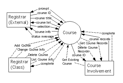
Things are complicated by the fact that there is a user of this system called a ``Registrar,'' and another class called ``Registrar'' as well. A terminator is shown here (with its name extended, to make its role clearer), for each of these.
Now, we'll have a ``context diagram'' for each of the classes in the system, and possibly a ``context diagram'' for the entire system, as well. Of course, these should all be consistent.
For example, since the above context diagram for ``Course'' includes a terminator for the class ``Course Involvement,'' the context diagram for ``Course Involvement'' should include a terminator for ``Course.'' Since a control flow labeled ``Get Existing Course'' is shown on the above diagram as going from the ``Course Involvement'' terminator into the ``Course'' process, a control flow labeled ``Get Existing Course'' should be shown on the context diagram for ``Course Involvement,'' and it should go from the ``Course Involvement'' process to the ``Course'' terminator, on that diagram.
If a ``system-level'' context diagram has been included, and (as in the diagram shown above) we've included ``terminators for external users'' on the context diagrams for classes, then there must be a conservation of data flow for the data flowing to and from terminators on these diagrams, as well. In particular, each terminator on the ``system level'' context diagram should be a terminator on the context diagram for at least one class, and each terminator on a context diagram for a class, that doesn't correspond to another class, should also be a terminator on the system-level context diagram.
The data flows should be preserved, as well. For example, since a data flow called ``prompt'' is shown on the context diagram for ``Class,'' and it is sent to the terminator for the system user, ``Registrar,'' there should be a data flow from the system to ``Registrar'' that is labeled ``prompt'' on the system-level context diagram, too. Conversely, each data flow (such as ``name'') that is shown as going to (or from) the ``Registrar'' on the system-level context diagram, should be showing as going to (or from) the terminator for the system user ``Registrar'' on the context diagram for at least one class. In this case, ``name'' isn't shown on the context diagram for ``Course;'' however, it would be shown on the context diagram for ``Student,'' if this had been included in these notes.
Now that we've introduced a context diagram for a class, we can introduce a leveled set of diagrams that refine this, too. This set should include a process for each service that the class (or object) provides; each process shown on the diagrams should either be refined by a lower level diagram, or by a process specification, but not both.
These lower level diagrams might include data stores, and a control process, as well as processes and data stores. The data stores would represent stored data that can be accessed by the ``internal'' processes included in the class, but that isn't accessible outside the class (except, through use of the services that the class provides). If there is a control process then you could specify it using a state-transition diagram; you'd do this if you discovered that the class had nontrivial states, that could effect the behaviour of the class's services, and that could be changed when the services are performed.
For example, the ``level 1'' diagram for the class ``Course'' might be as follows. (You should be able to confirm that the rules for ``conservation of flow'' have been obeyed for this diagram and the context diagram for ``Course'' that is given above).
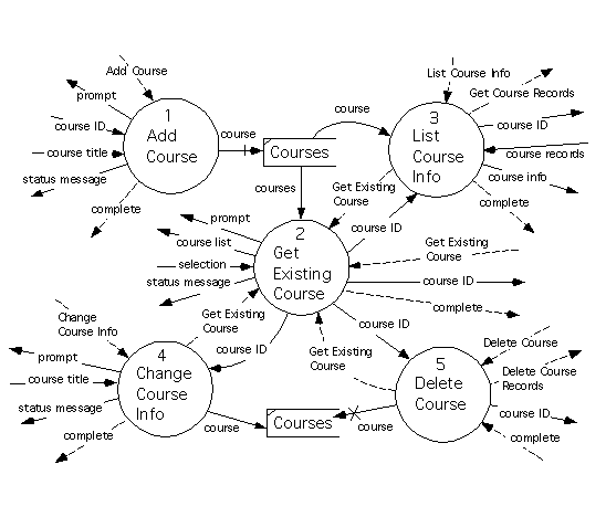
If you've provided a set of data flow diagrams for a class, then you should give a process specification for each of the ``bottom'' processes in the diagrams. These process specifications should resemble the process specifications you generate when using ``structured analysis.''
If you haven't provided data flow diagrams, then you should provide something like a ``process specification'' for each of the class's (and objects') services. Again, the format given for process specifications for structured analysis will probably be suitable here, as well.
As before, you should try to ensure that your process specifications are reasonably short and simple. If you can't give short and simple process specifications for services, then you should consider giving a leveled set of data flow diagrams for your class (so that you can use ``lower level data flow diagrams'' to specify your services), after all.
Location: [CPSC 333] [Listing by Topic] [Listing by Date] [Previous Topic] [Next Topic] Completing the Specification of Functional Requirements