
Location: [CPSC 333] [Listing by Topic] [Listing by Date] [Previous Topic] [Next Topic] Coad and Yourdon's Object-Oriented Analysis
This material was covered during lectures on February 10-14, 1997.
Components of a Class DiagramAn ``object-oriented specification'' of the type that can be developed using Coad and Yourdon's method includes a diagram that shows the ``problem domain'' classes the system will include, attributes and services, and various possible connections between classes.
Unfortunately, while Coad and Yourdon's pictures look nice, they aren't particularly easy to draw. In this class we'll use a simplified kind of ``class diagram'' with symbols that are easier to draw, and will leave some of the information (which Coad and Yourdon would include) off the diagram, and list it separately instead.
As defined by Coad and Yourdon, an object is an ``abstraction'' of something in the problem domain, reflecting capabilities of a system to keep information about it, interact with it, or both; and, an ``encapsulation'' of attribute values and their exclusive services.
An ``object'' corresponds (loosely) to an instance of an entity in an entity-relationship diagram.
A class is a description of one or more objects that have a uniform set of attributes and services, together with a description of how to create new objects in the class.
Things in the ``problem domain'' that might be represented as classes include the following.
Note that almost the same list was given for things in the problem domain that might be modeled by entities on an entity-relationship diagram.
Indeed, a class does correspond, loosely, to an entity in an entity-relationship diagram. However, things that might be represented in ``structured analysis'' as terminators on data flow diagrams, or as weak entities, supertypes or subtypes, or associative objects on entity-relationship diagrams might be represented as a class in a (Coad and Yourdon-style) object-oriented specification, as well.
On the other hand, there are some significant differences between classes in an object-oriented specification, and entities in an entity-relationship diagram. The most important of these are probably the following; more will be mentioned later.
Entities in an entity-relationship diagram (only) describe data that must be stored in order for the system to function correctly; classes may provide operations, or ``services,'' to the rest of the system, as well. Indeed, while classes usually do represent stored data, it's (occasionally) possible for a class to represent none at all, because it supports essential operations, instead.
Objects (in classes) are also ``dynamic,'' in the sense that that they can have ``states,'' just as states can be identified for systems when ``structured analysis'' is used to specify requirements.
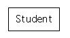
Consider, once again, Version One of the Student Information System; when constructing a ``class diagram'' for this system, we would probably include two classes - ``Instructor'' and ``Student,'' rather than just ``Student'' alone.
Coad and Yourdon draw classes as rectangles with rounded corners, and with an outer, grey, outline shown around an inner black one. The rectangles are frequently split into three horizontal slices, (roughly) as follows:
The top slice contains the name of the class (so, the class shown above has name ``Student,'' while the middle slice can be used to list attributes, and the bottom slice can be used to list services, once these are known.
These are difficult to draw; to save time, we'll just use a rectangle instead. We'll put the name of the class inside the rectangle, and we'll (eventually) list attributes and services, separately.
According to Coad and Yourdon, an attribute of a class is some data or state information, for which each attribute in a class has its own value.
Thus, an attribute of a class in object-oriented analysis resembles an attribute of an entity in an entity-relationship diagram. However, there are differences between attributes of classes and attributes of entities, that reflect the differences between classes and entities mentioned above, as well as the ones that follow.
Entities (and other components of entity-relationship diagrams) will be used design a system to manage the data that must be stored in order for the system to function - a system that can easily be implemented using either a ``relational data base,'' or a set of text files; on the other hand, systems specified using classes (and other components of an object-oriented specification) can be implemented using in a variety of ways. Some of the guidelines or rules concerning the creation of entity-relationship diagrams, that were motivated by the expectation that a ``relational data base'' would be used to implement the system being developed, don't apply to classes, etc.
When identifying attributes of entities (etc.) in an entity-relationship diagram, we insist that it's possible to choose a subset of the entity's attributes that can form a key. On the other hand, the problem of deciding how to identify objects in the same class is generally only considered during system design (that is, after problem-domain classes and objects have been specified), and we don't generally insist that ``keys'' (that are formed from ``problem domain attributes'') be used as the identification mechanism.
Now, significant differences between attributes in the two models, that reflect differences between ``classes'' and ``entities,'' include the following.
Rather than trying to cram a list of attributes for each class into part of a picture (as Coad and Yourdon do), we'll simply list the attributes of each class separately.
Instance connections on class diagrams are extremely similar to binary (two-way) relationships on entity-relationship diagrams: An instance connection between a pair of classes represents a set of connections between pairs of objects in the two classes, that the system must remember in order to function, and it represents no other information besides that.
If you add an instance connection on a class diagram, then you should decide at the same time (or, perhaps, a bit later - but before the ``requirements specification'' is completed) which of the classes it connects should ``take charge of it.'' That is, you should decide which of the two classes will ``keep track of'' the data that the instance connection represents (by containing ``something like'' an attribute that has a repeating group as its value) and will be responsible for creating and deleting instances of this connection, and telling the rest of the system whether a given pair of objects is connected by it, when this information is needed.
Sometimes, the type of the relationship, that the instance connection corresponds to, might be helpful in making this decision. For example, if the relationship is a ``one-to-many'' relationship, then it will often make sense to let the class whose instances can each participate in ``one'' instance of the connection take change of it, instead of the class whose instances can participate in ``many'' connections.
Following Coad and Yourdon, we'll draw instance connections as undirected connections (plain straight lines) between the pair of classes they connect. We'll also show how many ``instances of the instance connection'' each object in each class can participate in, by writing this down near the point where the straight line (representing the instance connection) touches the class (that the object belongs to).
Coad and Yourdon don't believe it's necessary to assign names to instance connections, unless there are multiple connections between the same pair of classes. However, a name is certainly allowed (and might give a reader a better idea of what the connection is supposed to represent); when a name is included, it is written on the class diagram near (just above, or just below) the line that represents the same instance connection.
Examples given in this course will usually assign names to instances connections.
For example, a class diagram for Version Two of the Student Information System would probably include two classes, ``Student'' and ``Course,'' (and at least one more, as well), and an instance connection, ``is registered in,'' between ``Student'' and ``Course.'' (It would include another instance connection, ``has passed,'' between these classes, as well, but this isn't shown here.)
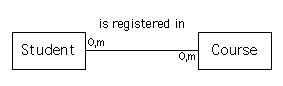
This shows that there is an instance connection, ``is registered in,'' that connects students to courses. Since the symbols ``0, m'' appear near the place where the line for the connection touches ``Student,'' we know that each student (object) can be connected to zero or more courses, via this connection. Similarly, since ``0,m'' also appears near ``Course,'' we know that each course (object) can be connected to zero or more students, as well.
When creating this, we'd need to decide whether ``Student'' should keep track of this instance connection, or whether ``Course'' would. Each choice seems just about as natural as the other, so (to begin with) we might make a fairly arbitrary choice, and allocate the responsibility to ``Course.''
As mentioned above, things that we'd represent as associative objects on entity-relationship diagrams are generally represented as classes on class diagrams. We also need to include a set of instance connections - one each for each of the ``entities'' that the ``associative object'' on the ERD was connected to, and that connects the ``class corresponding to the associative object'' to the ``class corresponding to the entity.'' It generally isn't necessary to name these instance connections, unless the associative object connects (instances of) the same entity to itself; in this last case, we could use something like the role each instance of the entity plays in the connection, in order to create useful names.
For example, a class diagram for Version Four of the Student Information System would probably include the following classes and instance connections, to show that a grade is something that is assigned to a student and to a section of a course, that each grade (object) is connected to exactly one student, while each student (object) can have zero or more grades connected to it, and that each grade (object) is also connected to exactly one course section, while each course section (object) can have zero or more grades (for students) connected to it.
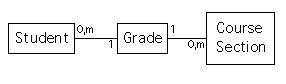
In this case, it probably makes sense to let the ``class representing the associative object'' (in this example, ``Grade'') take charge of all the instance connections that represent the associative object (along with it).
According to Coad and Yourdon, a service is a ``specific behaviour that an object is responsible for exhibiting.'' This can be thought of as an ``operation'' or ``function'' that the object (or class) provides for the rest of the system.
Services that ``a class'' must provide probably include ways to create new objects in the class and, perhaps, to list all (or some) of the objects that the class currently contains.
Services that an object in a class must provide will almost certainly include functions that report the values of the object's attributes, as well as functions that change at least some of these. There will generally be a function that can be used to ``delete'' or ``destroy'' an object. If an object has nontrivial ``states,'' then some of the object's services will cause the object's state to change. More ``algorithmically complex'' services, used to do things like prepare reports to be sent as output, may be needed as well.
While Coad and Yourdon show a way to list the names of services on their version of a ``class diagram'' (or, more accurately, they include the possibility of a ``service layer'' being shown when the diagram is displayed), we won't bother, and will always list services separately.
Objects (and, perhaps, classes) will almost certainly need to communicate with one another, in a nontrivial object-oriented system, in order to do useful work. A message connection on a class diagram is a directed connection (drawn using an arrow) from one class on the diagram to other, that points in the direction of some message can be sent between the classes, when the system is operating. Thus, there will be an arrow pointing from ``Class A'' to ``Class B,'' if class A can ask class B to perform one of the services that class B provides.
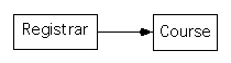
Consider, for example, Version Two of the Student Information System. Since this now involves multiple courses, it might be more reasonable to assume that this system is being used in a Registrar's office than that it's used by a single instructor, so we'll assume, now, that a ``Registrar'' is using the system. In this case, the class diagram for the system would include a ``Registrar'' class, as well as a ``Student'' class and a ``Course'' class.
This system will be used to change and display information about courses, so one of the ``events'' the system will be required to respond to (and that we'd identify if we were using structured analysis to specify requirements) would be a request from the registrar to view information about a given course - such as the course's ``course title.''
Now, a ``Registrar'' object in the object-oriented system is almost certainly responsible for receiving from the request from the ``outside world,'' while a ``Course'' object almost certainly provides the service that is needed in order to meet this request. Thus, a ``Registrar'' object must be able to send messages to ``Course'' objects, in order for the system to be able to respond to the above event. We'd show this by including a message connection from ``Registrar'' to ``Course,'' that would be drawn as follows.
Following Coad and Yourdon, we'd draw two arrows between these two classes - one pointing in each direction - if ``Course'' objects could send messages to ask that ``Registrar'' objects perform their services as well (rather, for example, than having a ``two-headed arrow'' between the two).
However, we wouldn't draw an arrow from Course to Registrar, just to show that the Course object will ``send an answer back'' to the Registrar, after the ``Course'' object has performed the service it was asked to. We also wouldn't show multiple message connections between ``Registrar'' and ``Course,'' even if the Registrar could send ``multiple kinds of messages'' to Course objects (perhaps, to request that multiple kinds of services be performed).
In systems that are as small as the ones that can be presented in this course, one might tend to find that almost every message connection that could exist, does actually exist, on the class diagram. This tends not to be the case with larger systems (or, at least, it shouldn't be the case, if the system has been correctly specified and designed); instead, classes will tend to send messages to and receive message from a relatively small set of others.
Finally, it should be noted that Coad and Yourdon also use arrows to draw message connections. However, they use arrow that are thicker than the one shown above, and their arrows are grey instead of black.
According to Coad and Yourdon, a structure is an expression of problem-domain complexity, pertinent to the system's responsibilities.
This definition might be unhelpful.... Fortunately, one can add that ``structures'' are different kinds of connections between (and organizations of) classes, and that there are two different kinds of structures that we should look for and show on class diagrams. Each of these is a bit easier to describe.
A ``generalization-specialization'' connection between classes on a class diagram conveys the same kind of information as showing that one entity is a supertype (or subtype) of another on an entity-relationship diagram - it shows that the more ``specialized'' class can be thought of as a kind of the more generalized one. On an entity-relationship diagram, this implies that all the ``generalized'' entity's attributes are inherited by the ``specialized'' one. On a class diagram, it means that the all the generalized class's attributes and services are inherited.
Now, once ``generalization-specialization'' structures are introduced, it can be convenient to introduce ``virtual classes'' on class diagrams - classes that are ``generalizations'' of several other classes on the diagram and that don't have any ``objects'' of their own (Put another way: Every ``object'' in the ``virtual class'' is also in one of the classes that are specializations of the virtual one). Coad and Yourdon draw a ``virtual class'' differently from a (regular) class, by leaving out the outer grey boundary that's included in their picture of a class.
We'll used a dashed box instead of a solid one, to draw a ``virtual'' class, instead. (Confession: This is notation that has been ``made up'' for this course, so you won't find it elsewhere; it's intended to be something that will be easy to use, in case you want to show a virtual class on a diagram that you make up for CPSC 333.)
For example, in Version Five of the Student Information System, both ``pass/fail courses'' and ``graded courses'' were supported. Every course was one of the above (but not both). Each of these two kinds of course were included as entities on the entity-relationship diagram for this system, and it was useful to include a third (virtual) entity, ``Course,'' that was a supertype of both, so that common attributes could be collected together and defined once (rather than twice). On a class diagram for the same system, one would need classes to represent both ``Pass/Fail Courses'' and ``Graded Courses,'' and, again, a ``virtual'' class, ``Course,'' could be introduced as a generalization of both:
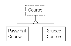
Note the ``half-circle'' connector used to denote a generalization-specialization structure. When possible, draw the generalization as centered above a row of its specializations, as is shown here.
One significant difference in these ``inheritance'' structures, in class diagrams and in ERDs, has already been noted: In class diagrams, services can be inherited along with attributes. Here is another: Multiple inheritance is allowed in class diagrams, so that a class can be a ``specialization'' of (and inherit attributes and services from) more than one other class. We'll see (if time allows) that multiple inheritance can be helpful during system design and implementation, and we want to have a class that ``inherits'' attributes and services from classes in (multiple) class libraries.
You can even have a class that is, indirectly, a generalization of another one in more than one way. For example, ``Vehicle'' might be a generalization of ``Aircraft'' and ``Boat,'' and both ``Aircraft'' and ``Boat'' might be generalizations of ``Hovercraft.'' When something like this happens, one copy of the generalization's (ie., Vehicle's) attributes and services are inherited by the specialization (ie, Hovercraft) - not several.
Finally, it should be noted that ``name conflicts'' can cause problems when multiple inheritance is used. That is, it's unclear what should happen if, for example, a class ``inherits'' two attributes with the same name, but different types, from two different ``generalizations.'' When possible, you should try to avoid this problem, by giving distinct names to all the attributes and services of classes on a diagram.
While ``generalization-specialization'' can be used to show that one class is a kind of another (and should inherit attributes and services), a ``whole-part'' structure can be used to show that an object of one class is a part of, or a ``component'' of, an object in another one.
Frequently, if two things in the problem domain would be represented by a weak entity and an entity that it depends upon, then they would also be represented on a class diagram that are part of a ``whole-part structure'' (with the class corresponding to a weak entity shown as ``a part of'' the class corresponding to the entity it depended on). However, ``whole-part'' structures are more general than this suggests, and one shouldn't try to decide whether it's possible to form ``keys'' from attributes, in order to form them. For example, you should use a ``whole part'' structure between classes representing assemblies (of components) and the components they include (eg, between ``Automobile'' and ``Engine''), or between classes representing departments or organizations, and the people who belong to (or work for) them (eg, between ``Academic Department'' and ``Faculty Member'').
For example, the class diagram for Version Three of the Student Information System would included classes with names ``Course,'' and ``Course Section'', and a ``whole-part structure'' that includes them (with ``Course Section'' shown as being a ``part'' of ``Course'').
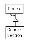
The ``connector'' used (which isn't displayed particularly well, here) is an isosceles triangle, pointing up towards the class corresponding to an ``assembly'' (the ``whole'' thing), and with a vertical line from the centre of the base of the triangle down to the class representing a ``component'' (the ``part'').
Note that multiplicities are shown here beside the ``assembly'' and the ``component'' classes, as well. The information shown in the above picture states that each ``Class'' object can have zero or more ``Course Section'' objects as components, while each ``Course Section'' object must be a component of exactly one ``Course'' object.
Finally, Coad and Yourdon introduce two ways to cope with class diagrams that would otherwise be too complex to be shown easily on a single page.
When a diagram contains a large number of classes, they recommend that you try to partition the classes into disjoint sets that they call ``subjects.'' Each subject is supposed to contain a set of classes that are logically related. They recommend that, when possible, you should try to group classes into sets, so that all the classes in a ``generalization-structure'' structure, or all the classes in a ``whole-part'' structure, or both, end up in the same ``subject.'' They also recommend that you try choose subjects so that the number of instance connections, and message connections, that cross ``subject boundaries'' are as small as possible.
A subject is shown on their diagrams by a closed curve that encloses all the classes in it. Coad and Yourdon give a ``subject number'' to each of their subjects; if they form k subjects from their classes, then the subject numbers used are 1, 2, ..., k. Coad and Yourdon's subjects are also given simple names, that are intended to describe the subsystem that each subject represents.
Using these, it becomes possible to introduce a new, more ``general'' (but less detailed) ``subject diagram,'' in which each subject is drawn as a small rectangle, with a grey outline, including the subject's number and name. This is generally small enough to be shown on a single page.
It is also generally possible to draw all the classes that are in a single subject on a single page, as well, so that subjects can be used to break a large class diagram down into a set of smaller (and simpler) ones, in a way that resembles (in some respects) the use of ``higher level'' and ``lower level'' data flow diagrams, in structured analysis.
Coad and Yourdon also recommend that you cope with complex diagrams by using a CASE tool that allows you to select which parts, or ``layers'' of the diagram you wish to see.
In particular, they introduce the notion of an ``attribute layer'' of a diagram, which includes the attributes and instance connections shown on the diagram, and a ``service layer'' which shows the services and message connections (as well as a ``class and object layer'' which draws in all the classes, showing only their names, and a ``subject layer'' showing the boundaries of the subjects), and suggest that you use several diagrams that show various layers separately (perhaps, one with the attribute layer but without the service layer, and another with the service layer but without the attribute layer), in order to avoid dealing with a single diagram that would be too cluttered to be understandable.
The diagrams used in this course will be two small for subjects to be worthwhile. Since we don't have access to the kind of CASE tool described above, we'll avoid clutter on our diagrams by leaving the names of attributes and services off them completely, as described above.
Location: [CPSC 333] [Listing by Topic] [Listing by Date] [Previous Topic] [Next Topic] Components of a ``Class Diagram''