|
|
VLAB Home |
|
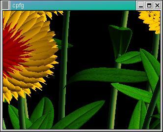
The use of textures can enhance the appearance of a model. Landmark features, such as veins on a leaf, must be placed properly on the surface. VLAB Texture Placement Editor allows the user to warp the texture on the surface, editing the texture image so as when it is mapped by the renderer (for example, CPFG) it will be properly placed. Figure 1 shows textures used in a model rendered in CPFG.
The Texture Placement Editor uses the Delauney triangulation algorithm. The convex hull is defined as the smallest convex polygon that completely encloses a set of points. A Delauney triangulation for a set of points can be calculated from the convex hull of a projection of the points onto a parabola in a space one dimension higher than that of the points themselves. When a point is added or deleted, a new triangulation is calculated. The image is scan-converted and warped within these triangles as the points are moved.
The VLAB Texture Placement Editor is invoked using the following command line arguments:
> warp [surface.s] [source_image.ppm] [destination_image.ppm]
The first argument is the surface file.
The second is the original image, that is to be warped onto the surface.
The third is the deformed image, that is generated by warping.
| Note: | Using the above arguments ensures that the original texture image is not modified. Of course, the original image can be overwritten with the deformed image by using the same filename for both arguments. |
The VLAB Texture Placement Editor consists of two windows: the Texture Warp Window and the Surface View Window. The Texture Warp Window displays the texture image. The image is shown actual size and cannot be resized. Points can be placed and moved in the Texture Warp Window. The Surface View Window allows the user to rotate, translate and zoom the surface in 3D space to view the placement of the texture. As the texture is modified, the surface is updated. There are different mouse operations in each window (refer to Table 4 and Table 5 for a list).
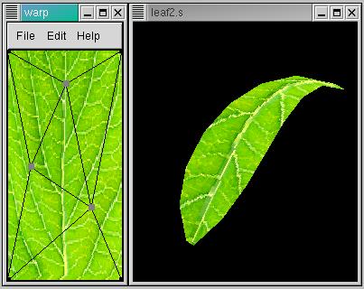
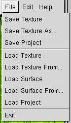
Figure 3 - The file menu. |
Table 1 - A description of the file menu. |
||||||||||||||||||
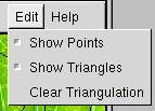
Figure 4 - The edit menu. |
Table 2 - A description of the edit menu. |
||||||||||||||||||

Figure 5 - The help menu. |
Table 3 - A description of the help menu. |
 |
Left button
|
 |
Middle button
|
 |
Right Button
|
|
Left button
|
|
Middle button
|
|
Right Button
|
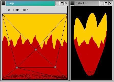
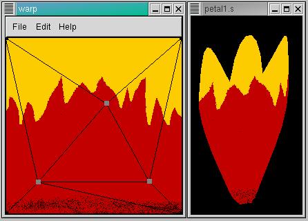
The following figures demonstrate how a control point can be moved to warp a texture on a surface. Notice the movement of the upper point upwards and to the right. Notice also how the texture is displaced on the surface, but only locally near the point that has been moved. The texture remains the same along the dark band at the bottom, for instance. The shape of the red border also remains the same.
The texture is simply an image file. The Texture Placement Editor works with two texture files: the original image and the deformed image.
The two texture files must be loaded at the command line. They can also be loaded or reloaded from within the application.
A surface file can be created using the Bezier Surface Editor. Refer to Bezier Surface Editor: Surface File Format.
The surface file must be loaded at the command line. It can also be loaded or reloaded from within the application.
A project file contains the control point and triangulation data. It can be generated by selecting Save Project from File menu.
A project file can be loaded at the command line only, and is optional.
Samantha Filkas, Joanne Penner - Texture Placement Editor Implementation vL1.0
Joanne Penner - Documentation vL1.0
1. The only file format supported for texture images is ppm. An image editing program, such as Gimp, can be used to convert between file formats.
|
|
VLAB Home |
|
